EMC D-SNC-DY-00 Dell SONiC Deploy Exam Exam Practice Test
Dell SONiC Deploy Exam Questions and Answers
How many ports are in each port-group on the S5200 series switches?
What interface must be selected when configuring the management port from within the MF-CLI environment?
Which network devices route unencapsulated user traffic in a symmetric IRB overlay network?
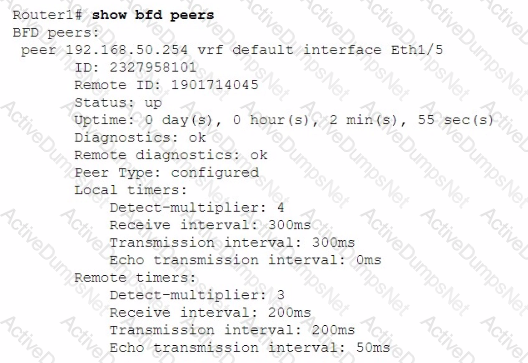
An administrator obtains the following CLI output:

How much time does the local system take to detect remote failures without receiving packets?
Which two elements are configured when RoCE is enabled?
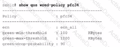
Refer to the exhibit.

What can be determined from this show command?
In what order should these commands be entered to configure an access port in SONiC CLI if the required VLAN is already configured?

Configure a VRF called "VrfGreen" and the static route in it to network 172.16.128.64/28 through next-hop 10.10.10.1. Set an administrative distance of 213.

Configure the system to meet these requirements.
. Configure R1 with AS 1.
. R1 must use a static neighbor assignment for BGP peering.
. R1 needs to redistribute all current and future connected IPv4 routes.
All the required BGP configurations have already been completed on R2.
R2 resides in BGP AS 2.


Use the simulator to perform the following configuration task.
1. Map a single-tagged CVLAN 100 to SVLAN 200 translation on PE
switch interface Eth1/1.
2. Map a double-tagged VLAN packet with an outer CVLAN 100 and an
inner dot1q 200 to SVLAN 300 translation on PE switch interface
Eth1/2.
The necessary VLANs and VLAN stacking have already been configured.

VLAN 40 is configured in Switch A with an anycast-address of 192.168.40.254/24. The ARP neighbor suppression is enabled. Use the simulator to create a VTEP named vtep1 and assign an IP address of
10.10.10.1. Map the VNI 400 to VLAN 40.

A customer must configure a peer link between two switches in the L2 MC-LAG scenario.
SwitchB has already been configured. Configure the peer link on SwitchA.
Use the following configuration information:
MC-LAG domain 1
VLAN 101
Peer link Port-Channel 100
SwitchA IP: 192.168.1.1/24
SwitchB IP: 192.168.1.2/24
MC-LAG system MAC: 00:00:00:11:11:11
The physical ports to connect the peer switch are Eth 1/5 and Eth 1/6 for each switch.


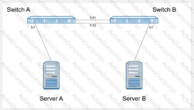
Create port channel 10 on interfaces Eth 1/11 and 1/12, so that it connects to an already configured switch. A server will be connected on Eth 1/1. Both the server and port channel need VLAN 1 untagged and only VLAN 10 tagged.
Complete the configuration on Switch A.


